Creates a single line object using the specified coordinate pairs. If you want to create an area, use the Polygon option instead. Even if you specify the first and last coordinate pairs to be the same, the type of the object generated will still be fme_line.
Creates an arc using the specified parameters.
The primary axis parameter specifies the length of the primary axis, and the secondary axis parameter specifies the length of the secondary axis. The start angle parameter specifies the start angle for the arc, measured in degrees counterclockwise from horizontal. The sweep angle parameter specifies the number of degrees on the ellipse that define the arc, measured in degrees counterclockwise. The rotation parameter specifies the angle in degrees from the horizontal axis to the primary axis in a counterclockwise direction. A circle can be created by setting the primary and secondary axis to the same length and using a sweep angle of 360 degrees.
Please note that not all transformers or output feature types work well with arcs. You may need an ArcStroker transformer to simplify it.
Creates an ellipse using the specified parameters. In order to create a circle, make sure the primary and secondary axes have the same length.
Please note that the ellipse generated by this is an arc feature. Not all transformers or output feature types can work with arc features, so you may need an ArcStroker transformer to simplify it.
Box
Creates a rectangular prism in 3D space. It is defined by a minimum corner and a maximum corner, but unlike a Rectangle Face, these two coordinates must not share identical x-, y-, or z-values.
The two corner points unambiguously represent a unique rectangular prism, in which all faces are parallel to the coordinate planes. If the first point is the minimum point, then the surface normal points out from the box; otherwise, the box has been flipped inside-out and the surface normal points into the box. With conjunction of a 4×4 transformation matrix, a Box can be used to represent boxes that are not parallel to the coordinate planes. This matrix can store affine transformations.
Rectangle Face
Creates an optimized rectangular face representation that lies parallel on a coordinate plane (either xy-, xz-, or yz-plane).
This face specifies its position by using two points, the minimum corner and maximum corner. Because the face must lie parallel to a coordinate plane, the corner points share a common coordinate value. For example, if the rectangular face lies on the xy-plane, the corner points share a common z-value. The surface normal of this rectangular face depends on the order of the specification of the first and second points, as described in the following table.
| Plane to which rectangle is parallel | Order of specification of (coordinates of) the corners | Direction of the surface normal |
|---|---|---|
| XY | Min-corner, max-corner | Positive Z-axis |
| YZ | Min-corner, max-corner | Positive X-axis |
| XZ | Min-corner, max-corner | Positive Y-axis |
| XY | Max-corner, min-corner | Positive Z-axis |
| YZ | Max-corner, min-corner | Positive X-axis |
| XZ | Max-corner, min-corner | Positive Y-axis |
The surface normal determines the orientation of the rectangular face; that is, the direction in which the surface normal points indicates which side is the front. With conjunction of a 4×4 transformation matrix, a Rectangle Face can be used to represent rectangular faces that are not parallel to the coordinate planes. This matrix can store affine transformations.
Creates a triangle strip, which is a series of connected triangular faces.
These faces are defined by three consecutive points in a point list. The first three vertices (labelled below as v1, v2, and v3), define the first triangular face. A new triangle is formed by connecting the next point with its two immediate predecessors. That is, every additional point vi defines a new triangular face with vertices vi–2, vi–1, and vi. For example, the second triangle is defined by v2, v3, v4, the third by v3, v4, v5, etc. The following diagram illustrates a typical Triangle Strip.
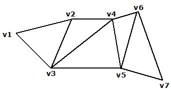
The orientation of the entire triangle strip is determined by the orientation of the first triangle. If the vertices of the first triangle are ordered counterclockwise, then the front of the strip is displayed; otherwise, the back of the strip is displayed. If the triangle strip has been flipped, then the front/back of the entire strip is actually the reverse of what the first triangle indicates.
Triangle Fan
Creates a triangular fan, which is a series of connected triangular faces. The fan differs from a Triangle Strip in the way that vertices define faces.
The first three vertices (labelled below as v1, v2, and v3), define the first triangular face. A new triangle is formed by connecting the next point with its immediate predecessor and the first point of the triangle fan. That is, every additional point vi defines a new triangular face with vertices v1, vi-1, and vi. For example, the second triangle is defined by v1, v3, v4, the third by v1, v4, v5, etc. The following diagram illustrates a typical Triangle Fan.
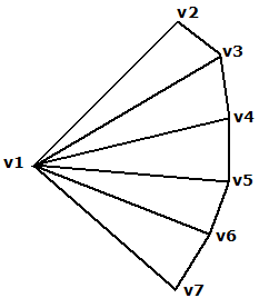
The orientation of the entire triangle fan is determined by the order of vertices of any triangle within the fan (all the triangles are already oriented in the same direction). When they are ordered counterclockwise, the front is displayed; otherwise, the back is displayed.
Creates a planar area in 3D space. The planar structure can be a polygon, an ellipse or a donut.
The orientation of a Face is determined by using the following rule: if the fingers of your right hand curl along the order of the vertices, the direction that the thumb points to is the front of the face. This thumb direction also describes the surface normal of the face, a vector that points outwards perpendicular from the area.
Curve closing method: This method controls how the curve is closed. It is applicable only if the first and last coordinates entered do not match X, Y or Z coordinate values. It ensures that the coordinates of the start and end points match so that it is a valid area.
Average: An additional point is added that connects the start and end point of the area. This point is computed by the average of the start and end points.
Extend: The start and end points are connected with no additional points.
Extend or Average Based on Z: The area is closed using the Average method if – and only if – the start and end points lie on the same coordinate plane (i.e. they share the same X, Y or Z coordinates). Otherwise, the Extend method is used to close the area.
Custom
Creates an object based on an XML representation.